English
 中文简体
中文简体

 2026-07-10
 Industry News
Content
An Electrocoating Paint Filtration System works by continuously drawing electrocoat bath liquid through semi-permeable ultrafiltration (UF) membranes under controlled pressure, separating low-molecular-weight contaminants including organic acids, dissolved salts, and co-solvents from the paint bath while retaining paint resin and pigment solids. The filtered liquid, called ultrafiltrate or permeate, is collected and redirected into the post-electrocoat rinsing cascade to recover drag-out paint from workpiece surfaces. The concentrated retentate returns to the electrocoat tank, completing a closed-loop circuit that simultaneously purifies the bath and recovers otherwise wasted paint material.
This continuous filtration and recovery loop serves two equally important functions: maintaining bath chemistry within the narrow operational windows required for consistent film quality, and capturing the paint dragged out of the tank on each processed workpiece rather than losing it to wastewater. In a modern automotive electrocoat system processing 60 to 80 vehicle bodies per hour, this system can recover paint valued at USD 300,000 to 500,000 annually while reducing electrocoat-contaminated wastewater generation by 80 to 90 percent (source: U.S. Environmental Protection Agency, Guides to Pollution Prevention, EPA/625/R-92/009, 1992).
Understanding why filtration is indispensable requires understanding what happens to the bath chemistry during continuous electrocoating production and why those changes, if uncontrolled, inevitably degrade coating quality.
During cathodic electrocoating, the most widely used configuration for automotive and industrial corrosion-protective primers, the workpiece serves as the negative electrode (cathode) and attracts positively charged paint resin particles from the bath. Simultaneously, the anode cells undergo oxidation reactions that continuously generate organic acids as the amine neutralizers used to solubilize the paint resin are released into solution when the resin deposits onto the workpiece. These acids dissociate to contribute hydrogen ions and organic anions to the bath, progressively increasing both bath conductivity and acidity.
Left uncontrolled, this acid and ion accumulation produces a cascade of quality failures:
The filtration system is the primary mechanism for maintaining the following bath parameters within their operational target ranges during continuous production:
| Bath Parameter | Typical Target Range | Consequence of Exceeding Range |
| pH | 5.8 to 6.5 | Below range: resin precipitation; above range: poor deposition efficiency |
| Conductivity | 800 to 1500 microsiemens/cm | High: film rupture at edges; low: insufficient film build |
| Co-solvent content | 1.5 to 3.0 percent by weight | High: soft film and sagging; low: orange peel and poor flow |
| Non-volatile solids (NVS) | 18 to 22 percent by weight | Low: insufficient film thickness; high: excessive drag-out |
| Bath temperature | 28 to 32 degrees Celsius | High: resin degradation; low: poor film flow and leveling |
Source: PPG Industries, Electrocoat Application Manual, 2018; Henkel Automotive Coatings Technical Guide, 2020.
The filtration system continuously removes the acid anions, dissolved salts, and excess solvents that drive conductivity and pH outside their target ranges, while the resin and pigment retained on the feed side of the membrane maintain the bath NVS within specification. This selective separation is the defining chemical function of the system.
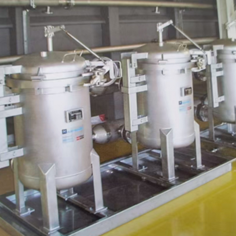
The ultrafiltration membrane is the heart of the electrocoating filtration system. Its pore size, material chemistry, and physical configuration determine precisely which components of the bath are retained and which pass through as permeate, making membrane selection critical to system performance.
Ultrafiltration membranes used in electrocoating operate in a pore size range of 0.005 to 0.05 micrometers, corresponding to molecular weight cutoff (MWCO) ratings of 20,000 to 100,000 Daltons. This range is specifically chosen to retain the paint resin and pigment particles, which range in size from 50 to 500 nanometers, while freely passing water molecules, organic acid anions, dissolved mineral salts, and alcoholic co-solvents, which are all orders of magnitude smaller than the membrane pore size. The selectivity of this separation is what makes UF membranes superior to conventional filters for electrocoat applications: they remove the problematic small molecules while preserving the valuable paint solids in the bath.
Four polymer membrane materials are used in electrocoat filtration, selected based on the specific pH range, temperature, and chemical environment of the bath chemistry:
| Material | pH Range | Max Temperature | Key Advantage | Typical Application |
| Polysulfone (PS) | 2 to 13 | 75 degrees C | Broad compatibility, proven track record | Cathodic and anodic systems, most common |
| Polyethersulfone (PES) | 1 to 14 | 95 degrees C | Higher temperature tolerance | High-temperature or aggressive chemistries |
| Polyvinylidene fluoride (PVDF) | 2 to 11 | 80 degrees C | Oxidant resistance, aggressive CIP tolerance | Systems requiring frequent chemical cleaning |
| Cellulose acetate (CA) | 3 to 8 | 50 degrees C | Low cost | Low-temperature, mild chemistry anodic systems only |
Source: Koch Separation Solutions, UF Membrane Material Selection Guide, 2021; Toray Membrane Technical Data Sheets, 2022.
Two membrane module geometries dominate electrocoat UF installations, each suited to different production scale and bath characteristic requirements:
A complete electrocoating filtration system comprises three distinct fluid circuits that operate simultaneously and in coordination to manage bath chemistry, recover drag-out, and supply the rinsing cascade.
The primary filtration circuit draws bath liquid from the electrocoat tank using a recirculation pump, pressurizes it to the membrane operating pressure (typically 1.0 to 3.5 bar transmembrane pressure), and passes it through the UF membrane modules in cross-flow mode. Cross-flow operation, in which the feed liquid flows tangentially across the membrane surface rather than perpendicularly through it, creates a shear stress at the membrane surface that continuously sweeps deposited paint particles away, preventing the rapid flux-blocking cake formation that would occur in dead-end filtration mode. The retentate stream, carrying all retained paint solids at slightly elevated concentration, exits the membrane modules and returns to the electrocoat tank. The cross-flow velocity is maintained at 1 to 3 meters per second across the membrane surface to sustain effective particle sweeping throughout the operating cycle.
The permeate that passes through the membranes is collected in a dedicated permeate tank, which acts as a buffer reservoir to smooth out short-term variations in permeate production rate relative to rinse demand. From the permeate tank, the ultrafiltrate is pumped to supply the post-electrocoat rinsing cascade in sequence:
The rinse bath liquid from the UF rinse stages, enriched with recovered drag-out paint solids, overflows back to the electrocoat tank or to an intermediate recovery tank, completing the paint recovery loop. This cascade architecture recovers 95 to 99 percent of the drag-out paint that would otherwise be wasted as wastewater contamination (source: Stahl, W.H. and Kurz, T., Ultrafiltration in Electrocoating, Progress in Organic Coatings, Vol. 38, 1999).
In cathodic electrocoating systems using membrane-separated anode cells, a dedicated anolyte circuit isolates the fluid surrounding the anodes from the main bath using ion exchange membranes. The anode oxidation reaction generates hydrogen ions and oxygen that acidify the anolyte. This anolyte fluid is continuously bled from the anode cells and replaced with fresh DI water, with the spent anolyte sent to pH neutralization and drain. The anolyte circuit removes the majority of electrode-generated acid before it can migrate into the main bath, complementing the UF system's role in maintaining bath pH. The two circuits together provide comprehensive bath chemistry management: the anolyte circuit handles electrode acid generation at the source, while the UF circuit handles the residual ionic and solvent accumulation across the full bath volume.
Permeate flux, expressed in liters per square meter of membrane area per hour (L/m2/h or LMH), is the primary operational performance indicator of an electrocoating UF filtration system. It determines whether the system produces sufficient permeate to supply the rinsing cascade at the required production rate and whether the bath chemistry bleed demand is being met.
Clean or freshly CIP-cleaned electrocoat UF membranes typically produce initial flux values of 40 to 80 LMH at design operating conditions. Steady-state operating flux during production, after the equilibrium fouling layer forms on the membrane surface, settles in the range of 20 to 50 LMH for most cathodic epoxy electrocoat systems. The difference between initial and steady-state flux reflects the formation of a reversible concentration polarization and fouling layer at the membrane surface that partially restricts permeate flow but remains removable by CIP cleaning.
Trending permeate flux against time is one of the most sensitive methods for detecting both membrane condition changes and bath chemistry deviations before they cause coating quality problems. A sudden flux drop accompanied by increased TMP indicates an acute fouling event, typically caused by resin precipitation or pigment agglomeration from a bath chemistry upset. A gradual flux decline over days signals normal progressive fouling approaching the threshold for scheduled CIP cleaning. Flux values that fail to recover above 60 percent of clean-membrane baseline after a full CIP cycle indicate irreversible fouling or membrane damage requiring module inspection and replacement.
Because membrane fouling is an inherent consequence of processing paint bath liquid through a semi-permeable membrane, regular cleaning in place (CIP) cycles are an essential operating procedure for any electrocoating filtration system. CIP is performed without removing membranes from service by circulating chemical cleaning solutions through the membrane circuit in a defined sequence.
A correctly executed CIP cycle on moderately fouled membranes typically recovers 80 to 95 percent of the original clean-membrane flux. CIP frequency in continuous automotive production is typically every 2 to 6 weeks, adjusted based on actual flux trend data rather than a fixed calendar schedule (source: GEA Filtration, Electrocoat UF Operating Manual, 2019).
Many modern electrocoat UF systems incorporate periodic automated backpulse sequences between full CIP cleans. A backpulse briefly applies pressure to the permeate side of the membrane for 0.5 to 3 seconds, reversing the transmembrane pressure and dislodging loosely adhered particles from the membrane surface. Backpulse sequences performed at 15 to 60 minute intervals extend the period between full CIP cleans and maintain operating flux up to 15 to 20 percent higher than continuous operation without backpulsing, reducing both cleaning chemical consumption and downtime associated with CIP cycles (source: Koch Separation Solutions, Backpulse Design Guide, 2020).
Although UF filtration is used in both anodic and cathodic electrocoating processes, the bath chemistry of each system creates distinct filtration demands and membrane compatibility requirements that must be matched in system design.
In cathodic systems, the bath operates in a mildly acidic range of pH 5.8 to 6.5. The primary contaminants requiring removal are organic acid anions (from amine counter-ion release), co-solvents (typically butanol, 2-butoxyethanol, or propylene glycol ethers), and lead or tin catalyst components in legacy formulations. Cathodic epoxy and acrylic-urethane chemistries provide corrosion protection exceeding 1000 hours in the ASTM B117 salt spray test for properly applied automotive primer thicknesses of 18 to 22 micrometers, making cathodic e-coat the near-universal choice for vehicle body corrosion protection (source: Electrocoat Association, Electrocoat Technology Overview, 2021).
Anodic systems operate at alkaline bath pH of 7.5 to 9.0, and the primary bath contamination mechanism is dissolution of metal ions from the workpiece surface at the anode, which can accumulate and destabilize the bath if not controlled. The alkaline operating environment requires UF membranes with verified stability at pH 9 and above, which polysulfone and polyethersulfone materials provide. Anodic e-coat is used for decorative applications including furniture, lighting fixtures, and architectural hardware where the moderate corrosion performance of anodic systems is adequate and the lower capital cost of anodic bath management is economically attractive.
Correctly sizing an electrocoating filtration system is critical to both coating quality and economic performance. An undersized system cannot maintain bath chemistry during peak production, leading to quality defects. An oversized system wastes capital and operating cost.
The required permeate production rate is determined by two independent demands that must both be fully supplied simultaneously:
Dividing the design permeate flow rate by the expected steady-state operating flux gives the required membrane area. Using a conservative steady-state flux of 30 LMH and a design permeate requirement of 340 liters per hour (after applying the safety margin), the required membrane area is approximately 11.3 m2. In practice, systems are built in discrete module increments, so the next standard module configuration above this calculated minimum is selected, providing additional flux buffer for future production rate increases.
Beyond its operational role in bath chemistry management, the electrocoating filtration system delivers measurable environmental and financial benefits that significantly improve the overall economics of electrocoating as a production process.
Without UF-based post-electrocoat rinsing, the paint film dragged out on each workpiece surface either dries and is discarded with rinse sludge or is diluted into the rinse wastewater and sent to treatment. A typical automotive e-coat bath has a paint solids cost of approximately USD 3 to 6 per kilogram. In a plant processing 1 million vehicle bodies per year with an average 3-liter drag-out per body at 20 percent NVS, the recoverable paint solids represent approximately 600 tonnes per year. At USD 4 per kilogram, the value of recovered paint is USD 2.4 million per year, representing one of the most direct and easily quantified financial returns from operating a properly functioning filtration system.
Electrocoat bath liquid that enters the rinse wastewater stream must be treated to remove organic paint solids, heavy metals (in legacy formulations), and chemical oxygen demand (COD) before discharge. UF rinsing reduces the paint solid content of the final DI rinse effluent to near-zero, dramatically reducing wastewater treatment chemical consumption, sludge generation, and treatment plant operating cost. Plants that have converted from conventional water rinsing to UF rinsing report wastewater treatment cost reductions of 60 to 80 percent for the electrocoat line specifically (source: EPA, Guides to Pollution Prevention, 1992).
Environmental regulations in most markets impose limits on COD, total organic carbon (TOC), and heavy metal concentrations in industrial wastewater discharge. The UF-based drag-out recovery system reduces the contaminant load on the plant wastewater treatment system, providing additional compliance margin that becomes increasingly valuable as regulatory standards tighten over time. Plants with marginal wastewater treatment capacity frequently find that optimizing UF filtration system performance is more cost-effective than expanding wastewater treatment infrastructure.
Systematic troubleshooting of filtration system problems prevents production interruptions and protects coating quality. The following table maps the most common system symptoms to their probable root causes and corrective actions:
| Observed Symptom | Most Likely Root Cause | Corrective Action |
| Rapid flux decline within days of CIP | Bath chemistry upset causing resin precipitation; pump operating below design flow | Verify bath pH, NVS, and solvent; check pump pressure and flow |
| Paint color visible in permeate | Membrane integrity failure (broken fiber or failed O-ring) | Perform pressure hold test; isolate and replace failed module |
| Permeate conductivity higher than bath | Membrane integrity failure allowing bath liquid to bypass membrane | Pressure hold test and module isolation as above |
| Permeate volume insufficient to fill rinse tanks | System undersized for actual production rate; membrane flux at end of service life | Confirm production rate vs design rate; measure flux and compare to CIP-cleaned baseline |
| Bath pH drifting low despite correct anolyte bleed | UF bleed rate insufficient; production rate increase beyond system capacity | Increase permeate bleed to drain; review production rate against system design parameters |
| CIP failing to restore flux above 50 percent of clean baseline | Irreversible membrane fouling or chemical damage to membrane polymer | Extended CIP soak attempt; membrane replacement if flux not recovered |
Source: Diagnostic framework adapted from GEA Filtration Electrocoat UF Service Guide, 2019, and Koch Separation Solutions Troubleshooting Manual, 2021.
The filtration system operates as an integrated subsystem of the complete electrocoating line. Its performance depends on and influences multiple upstream and downstream processes that must be managed holistically for optimal results.
Workpiece surface condition entering the electrocoat tank directly affects filtration system fouling rate. Workpieces carrying excessive pretreatment chemical carryover, residual machining oils, or loose metal particles introduce foreign contaminants that can cause acute fouling events in the UF circuit. Maintaining strict pretreatment rinse quality standards and drag-out control across the phosphating or zirconium conversion coating stages upstream of the electrocoat tank reduces the contamination load on the filtration membranes and extends CIP cleaning intervals.
The deionized water used to replenish evaporation and bleed losses must meet stringent purity specifications. Makeup water conductivity above 5 microsiemens/cm introduces mineral ions that accumulate in the bath and increase UF bleed demand. Calcium and magnesium hardness in makeup water deposits scale on membrane surfaces over time, reducing flux and degrading CIP effectiveness. Continuous monitoring of makeup DI water quality is therefore an important supporting maintenance practice for the filtration system.
Film quality defects detected after the cure oven frequently originate from bath parameter deviations that the filtration system is responsible for controlling. Edge pinhole and film rupture defects indicate excessive bath conductivity from insufficient acid removal. Poor film flow and orange peel texture indicate co-solvent content outside the target range. Treating these cured film defects as filtration system diagnostic signals rather than as isolated coating process problems enables root cause correction and prevents recurrence.
The Electrocoating Paint Filtration System solutions at jycoating.net are engineered for complete integration with full electrocoating line configurations, with system design encompassing membrane module selection, circuit sizing, permeate cascade design, CIP system specification, and control system integration matched to each installation's production rate, bath chemistry, and rinse quality requirements.
The electrocoating paint filtration system works through the continuous, coordinated operation of membrane separation, cross-flow circulation, permeate recovery, and chemical cleaning that together maintain the electrocoating bath in optimal condition and recover the economic value of drag-out paint:
2026-07-10
Industry News
2026-07-03
Industry News
2026-06-26
Industry News
2026-06-19
Industry News
2026-06-12
Industry News
2026-06-05
Industry News
For exclusive deals and latest offers, sign up by entering your email address below