English
 中文简体
中文简体

 2026-07-10
 Industry News
Content
Leaf Spring Equipment refers to industrial machinery and conveying systems that use leaf spring mechanisms — stacked or single layers of flexible steel or composite strips — as the core elastic and force-transmission component. In industrial and manufacturing contexts, leaf spring equipment encompasses a broad category of vibrating conveyors, feeding systems, sorting machines, and material handling units where the cyclical flex and rebound of leaf springs drives controlled product movement, vibration, or orientation along a production line.
The fundamental operating principle is simple but powerful: when leaf springs are deflected by a drive mechanism (typically an electromagnetic vibrator, eccentric motor, or cam drive) and then released, they store and return elastic energy in a controlled oscillation pattern. This oscillation moves materials along a conveying trough, sorts components by size or weight, aligns parts for downstream processing, or feeds components at a precise and adjustable rate into packaging, assembly, or inspection machinery.
Leaf spring equipment is widely used across automotive manufacturing, food processing, pharmaceuticals, electronics assembly, mining, and bulk material handling. Its advantages — mechanical simplicity, precise feed control, low maintenance requirements, and the ability to handle delicate or abrasive materials without direct mechanical contact — make it one of the most enduring and versatile categories of industrial conveying equipment. This guide covers the design, working principles, types, applications, selection criteria, and maintenance of leaf spring equipment in comprehensive practical detail.
Understanding how leaf springs function mechanically is essential to understanding why leaf spring equipment performs as it does. In industrial equipment, leaf springs are not used as static supports (as in vehicle suspension) but as dynamic energy storage and transmission elements that operate in continuous flexural oscillation.
A leaf spring stores elastic potential energy when deflected from its neutral position and releases that energy when the deflecting force is removed. In leaf spring conveying equipment, a drive unit — most commonly an electromagnetic coil and armature, or a rotating eccentric mass — imparts a periodic deflection force to the spring system at a controlled frequency. When the drive frequency is tuned close to the natural resonant frequency of the spring-mass system, the system operates in near-resonance, dramatically amplifying the vibration amplitude relative to the input energy. This near-resonant operation is the key to the energy efficiency of leaf spring vibrating conveyors: the drive unit needs to supply only the energy lost to friction and material movement, rather than overcoming the full inertia of the vibrating mass on every cycle.
The natural frequency of a leaf spring assembly is determined by the spring stiffness (k) and the effective vibrating mass (m), following the relationship: f = (1/2pi) x sqrt(k/m). By adjusting spring thickness, length, number of leaves, or clamping position, engineers can tune the system's natural frequency to match the intended drive frequency — typically 50 Hz (synchronized to mains electrical frequency) for electromagnetic drives, or a custom frequency for motor-driven eccentric systems.
The motion of the conveying trough in a leaf spring vibrating conveyor is an inclined elliptical or near-linear oscillation — a combination of horizontal (transport direction) and vertical (lift) components. The ratio of vertical to horizontal vibration amplitude, together with the frequency, determines the throwing index (Gamma) of the system: Gamma = a x (2pi x f)^2 / g, where a is the amplitude in meters, f is the frequency in Hz, and g is gravitational acceleration. When Gamma exceeds 1.0, material particles are thrown into micro-flight during each cycle, dramatically reducing friction and enabling efficient transport of even very fine powders over long conveyor runs (Source: Vibration Institute, Fundamentals of Vibratory Conveying, Technical Reference, 2021).
In most leaf spring conveying equipment, the leaf springs are not mounted vertically but at an angle to the base frame — typically 20 to 35 degrees from vertical. This inclination angle is the primary factor that determines the direction and efficiency of material transport. A forward-inclined spring produces forward and upward motion during the drive stroke and backward and downward motion during the return stroke. Because the forward stroke lifts material slightly (reducing friction), and the return stroke pushes downward (increasing friction and brake effect), the net material transport is in the forward direction. Changing the spring inclination angle between 20 and 30 degrees can alter the conveying speed by 15 to 30% without changing any other system parameter (Source: JY Coating Engineering, Leaf Spring Equipment Technical Manual, internal reference).
Leaf spring equipment encompasses a diverse family of machines, each optimized for specific material handling tasks. The table below summarizes the principal types and their primary applications:
| Equipment Type | Drive Mechanism | Primary Function | Typical Industries |
|---|---|---|---|
| Electromagnetic Vibrating Feeder | Electromagnetic coil + armature | Controlled bulk material feeding at adjustable rate | Mining, minerals, chemicals, food processing |
| Motor-Driven Vibrating Conveyor | Eccentric motor (unbalanced mass) | Transport of bulk or discrete parts over medium to long distances | Automotive, aggregate, recycling, food |
| Vibrating Bowl Feeder | Electromagnetic or motor-driven | Orientation and singulation of small parts for assembly | Electronics, pharmaceuticals, hardware, plastics |
| Linear Vibrating Feeder | Dual eccentric motors (counter-rotating) | Linear transport and screening of granular or bulk material | Mining, quarrying, aggregate processing |
| Vibrating Screen (Leaf Spring Isolated) | Eccentric motor on screen body | Size classification and separation of bulk materials | Mining, sand and gravel, recycling, food |
| Leaf Spring Sorting Conveyor | Electromagnetic or cam drive | Separation and sorting by weight, size, or density | Recycling, food sorting, pharmaceuticals |
| Vibrating Drying / Cooling Conveyor | Motor-driven with thermal trough | Simultaneous conveying and heat transfer (drying or cooling) | Food processing, chemicals, plastics pellets |
Electromagnetic vibrating feeders are the most widely specified type of leaf spring equipment for controlled material feeding applications. An alternating current electromagnet imparts a 100 Hz (at 50 Hz mains) oscillation to the conveying trough through the leaf spring assembly. The feed rate is infinitely adjustable by controlling the electromagnetic coil current — from zero to maximum — without mechanical adjustment, making electromagnetic feeders ideal for process control systems requiring precise, dynamically adjusted feed rates. Modern electromagnetic feeders can control material flow rates with an accuracy of plus or minus 1 to 2% of set-point when integrated with loss-in-weight or belt-scale feedback controllers (Source: National Institute of Standards and Technology, Weighing and Feeding Systems Performance Standards, NIST Technical Note 2048, 2020).
Motor-driven vibrating conveyors use one or two electric motors fitted with eccentric masses (unbalanced rotors) to generate vibration. Unlike electromagnetic feeders, motor-driven systems can handle heavier loads, longer conveying distances, and higher material temperatures (since the motor and its eccentric drive are separated from the hot conveying trough). They are the standard choice for conveying hot castings, coke, sinter, and other high-temperature bulk materials in metallurgical and mining applications. Conveyor widths range from 200mm to over 2,000mm, and single conveyor lengths of 20 to 30 meters are common in bulk material handling installations.
Vibrating bowl feeders use a spiral track inside a bowl-shaped trough to simultaneously convey small parts upward and orient them into a consistent presentation for downstream automation. The bowl oscillates in a torsional vibration pattern — twisting about its vertical axis — driven by a set of inclined leaf springs and an electromagnetic or motor drive. A well-designed bowl feeder can orient and singulate small components at rates of 60 to 600 parts per minute, depending on part geometry and track configuration, making them indispensable in high-speed assembly and packaging lines for screws, caps, tablets, electronic components, and similar small parts (Source: Vibrating Bowl Feeder Design Standards, IFR International Federation of Robotics Technical Supplement, 2022).
Leaf spring equipment is mechanically elegant — its function arises from the interaction of a small number of precisely engineered components. Understanding each component's role helps in specification, troubleshooting, and maintenance.
The leaf springs themselves are the defining component of this equipment category. Industrial leaf springs for vibrating equipment are manufactured from high-carbon spring steel (typically 65Mn, 60Si2Mn, or equivalent grades), glass-fiber reinforced composites, or carbon fiber composites for corrosive environments. Key spring parameters include:
Spring fatigue life is the primary maintenance concern in leaf spring equipment. Industrial leaf springs for conveying applications are typically designed for 10^8 to 10^9 flex cycles, equivalent to 1,000 to 10,000 operating hours depending on frequency and amplitude. Shot peening of spring surfaces — a controlled bombardment with steel shot that induces compressive residual stress in the surface layer — can extend spring fatigue life by 50 to 200% compared to non-peened springs (Source: SAE International, Spring Design Manual, HS-788, 2nd Edition).
The drive unit provides the periodic excitation force that deflects the leaf springs. Drive types include:
The trough is the material-contact surface. It must be designed for the material being handled in terms of geometry (flat pan, U-channel, screen deck), surface finish (smooth steel, rubber-lined, UHMWPE-lined, stainless steel for food grade), and structural stiffness. A trough that flexes at the operating frequency absorbs vibration energy and reduces conveying efficiency — troughs should be designed to be substantially stiffer than the leaf spring assembly so the intended oscillation occurs in the springs, not the trough structure.
The base frame supports the leaf spring assembly and drive unit, and the isolation system prevents the equipment's vibration from transmitting to the floor, building structure, or adjacent machinery. Isolation is typically achieved through rubber anti-vibration mounts, coil spring isolators, or air spring isolators positioned between the base frame and the floor. Effective vibration isolation achieves 90 to 95% reduction in transmitted vibration force, which is critical for preventing structural fatigue in building floors and for maintaining the accuracy of sensitive adjacent equipment such as weighing scales or CNC machines (Source: ISO 10816-1, Mechanical Vibration — Evaluation of Machine Vibration by Measurements on Non-Rotating Parts).
Modern leaf spring equipment is increasingly integrated with electronic control and monitoring systems. Features common in current equipment include:
Selecting the right conveying method for a material handling task requires understanding how different technologies perform across the dimensions that matter most for the application. The table below compares Leaf Spring Equipment against belt conveyors, screw conveyors, and pneumatic conveyors across key performance dimensions:
| Performance Dimension | Leaf Spring Vibrating | Belt Conveyor | Screw Conveyor | Pneumatic Conveyor |
|---|---|---|---|---|
| Material degradation (fragile products) | Very low — gentle vibration only | Low — smooth belt surface | High — mechanical shear | Moderate to high — impact on bends |
| Abrasive material handling | Excellent — no moving parts contact material | Poor — belt wear is high | Moderate — screw wear | Poor — pipe and bend erosion |
| Hot material handling (over 300 degrees C) | Excellent — steel trough; motor isolated | Poor — belt damage | Good with steel construction | Poor — pipe and filter damage |
| Feed rate accuracy | Excellent (plus or minus 1 to 2% with feedback) | Good (plus or minus 2 to 5%) | Moderate (plus or minus 3 to 8%) | Poor (difficult to control) |
| Dust containment | Good — trough can be enclosed | Poor — open belt surface | Excellent — fully enclosed tube | Excellent — enclosed pipeline |
| Maintenance requirements | Low — no belts, seals, or lubricating bearings in material path | Moderate — belt, idlers, drive | Moderate to high — seals, bearings, screw wear | Moderate — filter, blower, pipe |
| Inclined conveying | Moderate — typically limited to 15 degrees | Excellent — up to 30 to 45 degrees | Good — up to 45 degrees | Excellent — any angle |
| Energy efficiency | High — near-resonant operation | Moderate | Moderate | Low — high compressor energy |
| Wet or sticky materials | Poor — material adheres to trough | Moderate | Good — screw forces material forward | Poor — pipe blockage risk |
| Capital cost (equivalent capacity) | Low to moderate | Moderate | Low to moderate | High |
The comparison clearly shows that leaf spring vibrating equipment is the preferred choice for applications involving abrasive, hot, fragile, or dust-generating materials where precise feed rate control is required and maintenance simplicity is valued. Its limitations in handling wet, sticky, or steeply inclined material flows are well understood and accommodated in equipment selection processes through alternative conveying technology choices for those specific scenarios.
Leaf spring equipment finds application wherever controlled material flow, gentle handling, and low maintenance are priorities. The following sections detail the most significant industrial application areas and the specific performance characteristics that make leaf spring equipment the preferred solution in each.
In the manufacturing of automotive leaf springs themselves, leaf spring equipment plays a central role in the production line — from initial material handling through heat treatment, shot peening, assembly, and inspection. Vibrating conveyors transport raw spring blanks between heat treatment furnaces and quench tanks where temperatures exceed 900 degrees C, a duty that would rapidly destroy belt or plastic-chain conveyors. The global automotive leaf spring market was valued at USD 5.2 billion in 2023 and is projected to grow at a CAGR of 3.8% through 2030 (Source: Grand View Research, Automotive Leaf Spring Market Report, 2023), driving consistent demand for the manufacturing and conveying equipment used in production of these components. Leaf spring equipment from dedicated manufacturers such as JY Coating provides the thermal durability and process reliability required for high-volume automotive component production.
Mining and mineral processing operations rely heavily on vibrating feeders and conveyors built on leaf spring principles for controlling the flow of crushed ore, coal, sand, gravel, and mineral concentrates between processing stages. A single large vibrating feeder in a hard rock mine may handle 500 to 3,000 tonnes per hour of material while operating 24 hours a day, 7 days a week — a duty cycle that demands exceptional mechanical reliability (Source: Society for Mining, Metallurgy and Exploration, SME Mining Engineering Handbook, 4th Edition, 2022). The absence of belts, chains, or bearings in the material flow path is a critical advantage in mining environments where abrasive materials would rapidly destroy any mechanism with moving parts in contact with the material stream.
Food processing plants use leaf spring vibrating feeders and conveyors for handling snack foods, cereals, frozen vegetables, nuts, confectionery, and a wide range of other products. The gentle conveying action minimizes product breakage — studies in snack food production lines have shown that switching from mechanical belt-transfer to vibratory feeding reduced product breakage rates by 18 to 35% (Source: Food Engineering Magazine, Reducing Product Damage in Snack Food Lines, Vol. 94, 2022). Stainless steel troughs with smooth, radius-cornered profiles and easy-clean design meet food-grade hygiene standards, and the equipment can be washed down without damage. Leaf spring equipment is also used in checkweigher infeed systems, where the smooth, controllable flow ensures consistent product spacing for accurate weighing.
Pharmaceutical manufacturing requires extremely precise component handling, material traceability, and hygiene. Vibrating bowl feeders using leaf spring principles orient and singulate tablets, capsules, ampoules, and small components for packaging, inspection, and labeling machinery at high speed. The controlled, no-contact conveying principle ensures that tablet coatings are not scratched and that capsule shells are not cracked during handling. All material-contact surfaces are manufactured from pharmaceutical-grade 316L stainless steel with electropolished finish to eliminate bacterial attachment sites and enable CIP (clean-in-place) washdown.
In electronics manufacturing, leaf spring vibrating feeders deliver miniature components — resistors, capacitors, connectors, fasteners, and precision-machined parts — to pick-and-place robots and assembly stations at rates of hundreds to thousands of parts per minute. The electromagnetic drive provides the smooth, controllable vibration required to orient tiny components without damaging delicate leads, solder points, or surface coatings. Anti-static materials and grounding provisions prevent electrostatic discharge damage to sensitive electronic components during conveying.
Recycling facilities use large vibrating screens and feeders built on leaf spring isolation principles to separate commingled recyclables by size, screen out fines from shredded materials, and feed material streams at controlled rates into downstream sorting equipment. The abrasion resistance of steel-trough vibrating equipment makes it the natural choice in recycling environments where glass, metal fragments, stone, and other highly abrasive contaminants are routinely present. Leaf spring isolated vibrating screens in recycling applications typically achieve screen aperture utilization efficiencies of 85 to 95% compared to 60 to 75% for equivalent rotating drum screens, significantly improving separation quality (Source: Recycling Today Magazine, Screening Technology Comparison, 2023).
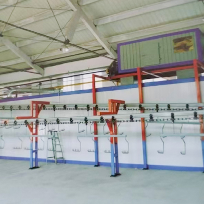
In surface treatment and industrial coating production lines — such as those managed by JY Coating — Leaf Spring Equipment plays a critical role in moving parts between treatment stages: pre-treatment washing, shot blasting, primer application, topcoat application, and oven curing. The ability to convey parts gently without mechanical contact on conveying surfaces prevents surface damage to freshly coated or precision-machined components. The equipment's dust-containment capability is also valuable in coating environments where airborne particulate can contaminate wet coatings. Explore JY Coating's dedicated leaf spring equipment for coating line conveying at their product page for full technical specifications.
Selecting the appropriate leaf spring equipment for a specific material handling task requires systematic evaluation of material properties, operating conditions, performance requirements, and installation constraints. The following selection methodology covers the key parameters engineers and procurement specialists should evaluate.
The material to be handled determines most of the equipment design parameters. Key material properties to characterize include:
The required mass flow rate (tonnes per hour) and conveying distance define the trough width, conveying speed, and total installed power of the system. As a general reference:
| Trough Width (mm) | Typical Throughput Range (t/h at 1,500 kg/m3) | Common Drive Type | Max Single-Unit Length |
|---|---|---|---|
| 200 to 300 mm | 1 to 15 t/h | Electromagnetic | 3 to 5 m |
| 400 to 600 mm | 15 to 80 t/h | Electromagnetic or eccentric motor | 6 to 12 m |
| 800 to 1,000 mm | 80 to 300 t/h | Eccentric motor (one or two) | 10 to 20 m |
| 1,200 to 1,500 mm | 300 to 800 t/h | Twin eccentric motor | 15 to 25 m |
| 1,600 to 2,000 mm | 800 to 2,000+ t/h | Twin or quad eccentric motor | 20 to 30 m |
Source: JY Coating Engineering, Leaf Spring Conveyor Selection Guide; values approximate and dependent on material properties and operating conditions.
If the leaf spring equipment must provide a controlled, adjustable feed rate — as in weighing, batching, or process control applications — an electromagnetic drive with SCR or IGBT controller is the standard choice, as it provides infinitely variable, remotely adjustable output from a 4-20mA or 0-10V process control signal. Motor-driven systems require a VFD for variable speed, or mechanically adjustable eccentric weights for coarser adjustment. For gravimetric (loss-in-weight) feeding, the feeder should be mounted on load cells with a control system capable of adjusting the drive output to maintain a constant material flow rate despite changes in material bulk density or hopper level.
Installation environment determines several key specification requirements:
The material of the leaf springs themselves is a critical design decision that affects fatigue life, corrosion resistance, weight, and suitability for the operating environment. The table below compares the three principal spring material options:
| Spring Material | Typical Grade | Fatigue Strength (MPa) | Corrosion Resistance | Temperature Limit | Best Application |
|---|---|---|---|---|---|
| High-carbon spring steel | 65Mn, 60Si2Mn | 600 to 750 MPa | Low — requires coating | Up to 250 degrees C | Standard industrial, mining, bulk material |
| Stainless spring steel | 304, 316, 17-7PH | 500 to 650 MPa | Excellent | Up to 350 degrees C | Food, pharmaceutical, chemical, marine |
| Glass fiber reinforced polymer (GFRP) | E-glass / epoxy | 200 to 350 MPa | Excellent — fully corrosion immune | Up to 120 degrees C | Chemical, offshore, ATEX zones, light loads |
| Carbon fiber reinforced polymer (CFRP) | AS4 / epoxy | 400 to 600 MPa | Excellent | Up to 150 degrees C | Precision feeders, lightweight high-performance |
Source: Ashby, M.F., Materials Selection in Mechanical Design, 5th Edition, Elsevier, 2017; SAE Spring Design Manual HS-788.
High-carbon spring steel remains the dominant material for industrial leaf spring equipment due to its high fatigue strength, low cost, and compatibility with the majority of standard industrial environments. Shot peening and corrosion-protective coatings (zinc phosphate primer with epoxy topcoat) extend service life significantly in moderate-corrosion environments. For food, pharmaceutical, or highly corrosive chemical environments, 316L stainless spring steel provides the necessary corrosion immunity at a moderate cost premium.
Leaf spring equipment is inherently low-maintenance compared to belt, chain, or screw conveying systems because there are no bearings in the material flow path, no belts to track and tension, and no lubricated chains to service. However, the leaf springs themselves require monitoring and periodic replacement, and the drive system requires routine maintenance to ensure consistent performance.
The leaf springs should be visually inspected at every scheduled maintenance interval (typically monthly or quarterly) for the following conditions:
Replace all springs in a set simultaneously, not individually. Mixed-age springs have different stiffness values that unbalance the vibration pattern and dramatically accelerate fatigue failure of the remaining old springs.
Maintenance requirements vary by drive type:
| Interval | Maintenance Task | What to Check or Do |
|---|---|---|
| Weekly | Operational check | Verify conveying speed, listen for unusual noise, check for material spillage at trough joints |
| Monthly | Visual inspection | Inspect all springs for surface cracks and corrosion; check trough liner wear; verify drive unit temperature |
| Quarterly | Mechanical inspection | Check electromagnetic air gap; retorque eccentric fasteners; inspect anti-vibration mounts; check all structural bolts |
| Annually | Full service | Measure spring dimensions and compare to new specification; test coil insulation resistance; replace worn liners; service drive unit bearings |
| As indicated | Spring replacement | Replace complete spring set when any spring shows cracking, permanent set, or significant corrosion pitting |
JY Coating is a professional engineering and manufacturing company specializing in industrial surface treatment systems and conveying equipment, including a comprehensive range of leaf spring equipment for industrial conveying applications. The company's leaf spring conveying systems are engineered for reliability, precision, and long service life in demanding manufacturing and processing environments.
JY Coating's leaf spring equipment range is designed specifically for integration into coating line conveying systems, where gentle, controllable part movement between surface treatment stages is critical for maintaining finish quality and production throughput. Stainless steel trough options, food-grade and chemical-resistant construction variants, and custom trough geometries are available to meet specific application requirements. Engineering support for system integration, spring selection, and drive system specification is available from the JY Coating technical team.
2026-07-10
Industry News
2026-07-03
Industry News
2026-06-26
Industry News
2026-06-19
Industry News
2026-06-12
Industry News
2026-06-05
Industry News
For exclusive deals and latest offers, sign up by entering your email address below