


 2026-07-17
 Industry News
Content
An electrophoretic coating filtration system works by continuously circulating the electrocoat paint bath through a series of filtration stages that remove solid contaminants, control ionic concentration, regulate pH, and maintain the chemical balance of the tank solution — all while the electrophoretic deposition process is running. The system ensures that the bath remains free of particles, metallic ions, and chemical byproducts that would otherwise cause coating defects such as pinholes, surface roughness, cratering, or poor film adhesion.
The filtration process operates in parallel with the electrophoresis itself: the bath solution is drawn from the main tank by a circulation pump, passed through mechanical bag or cartridge filters that capture solid impurities, then through ultrafiltration (UF) membranes that separate low-molecular-weight contaminants and excess ions, before the cleaned solution is returned to the tank. The ultrafiltered permeate — called UF filtrate or permeate — serves a dual purpose: it is used as a rinse liquid in the post-dip wash stages to recover drag-out paint and reduce wastewater load, and its controlled removal helps maintain the ionic balance of the bath.
This combination of mechanical filtration, membrane ultrafiltration, and controlled ion removal allows electrophoretic coating lines to run continuously for extended periods — often months between major bath changes — while consistently producing defect-free coatings on automotive bodies, appliances, hardware, and industrial components.
Electrophoretic coating — also called electrocoating, e-coating, or electrodeposition — is a process in which electrically charged paint particles dispersed in a water-based bath are deposited onto a conductive workpiece by the application of a DC voltage. The process is highly sensitive to bath chemistry: even small deviations in particle size distribution, ionic concentration, pH, or contamination level can cause visible defects in the deposited film.
Several contamination mechanisms continuously degrade the bath during production:
Without a continuously operating filtration system, contamination would accumulate to unacceptable levels within hours or days of operation, making consistently defect-free coating impossible. The filtration system is therefore not an optional accessory but a core functional component of any production-scale electrocoating line.
A complete electrophoretic coating filtration system typically incorporates multiple sequential stages, each targeting a specific type of contaminant or chemical imbalance. Understanding each stage individually clarifies how the overall system achieves the bath purity required for consistent coating quality.
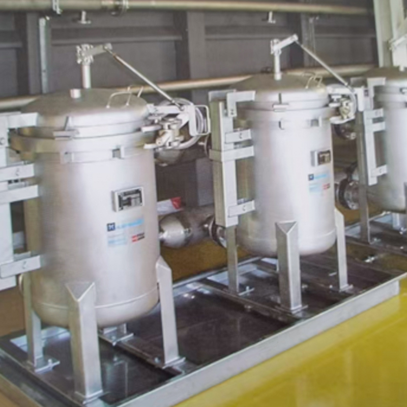
The first filtration stage removes solid particles above a defined size threshold from the circulating bath. In most electrocoating systems, this is accomplished using bag filters housed in stainless steel filter vessels. Stainless steel construction is essential because the electrocoat bath is chemically aggressive — standard carbon steel would corrode rapidly and introduce iron ions that contaminate the bath.
Modern electrocoat filtration employs a multi-tube parallel design, in which multiple filter bags operate simultaneously within a single housing or across multiple parallel housings connected to the same circulation circuit. This configuration provides several critical advantages:
Bag filter ratings for electrocoat applications are typically in the range of 25 to 100 microns for the first-stage coarse filter, capturing rust particles, dirt, and agglomerated paint solids that would cause visible coating roughness if allowed to remain in the bath.
Following coarse bag filtration, the bath flow passes through fine cartridge filters rated at 1 to 10 microns. These remove smaller particles that passed through the bag filters — including fine metallic debris, agglomerated paint micro-clusters, and inorganic contamination from the pre-treatment process.
Cartridge filters for electrocoat applications are typically constructed from polypropylene, polyester, or other chemically resistant materials. Pleated cartridge designs are preferred over wound configurations because their higher surface area per unit volume extends service life and maintains lower differential pressure across the filter as solids accumulate.
The fine filtration stage is particularly important for achieving high-gloss topcoat quality. Particles larger than approximately 5 microns are large enough to create visible surface texture when deposited under the electrocoat film. In automotive primer applications where the paint film thickness is typically 15 to 25 microns, a single 10-micron particle can create a protrusion visible to the eye and detectable by automated surface inspection systems.
Ultrafiltration (UF) is the most technically sophisticated and functionally critical stage of the electrocoat filtration system. UF membranes have pore sizes in the range of 0.001 to 0.1 microns (1 to 100 nanometers), which is small enough to retain paint resin particles and pigment clusters while allowing water, dissolved ionic species, low-molecular-weight organic compounds, and solvent residues to pass through as permeate.
The UF stage operates on the principle of cross-flow filtration: the bath solution flows tangentially across the membrane surface rather than perpendicularly into it. This cross-flow sweeps accumulated solids off the membrane face, preventing rapid cake formation and maintaining consistent permeate flux over long operating periods. A portion of the flow — typically 10% to 30% — passes through the membrane as permeate (UF filtrate), while the concentrate (retentate) returns to the main bath tank.
The UF stage achieves several simultaneous functions:
Understanding the complete flow path of the filtration circuit helps clarify how all stages work together as an integrated system. The following describes the standard circuit configuration used in cathodic electrocoat (CED) systems, which account for the majority of automotive and appliance electrocoating applications worldwide.
The entire circuit operates continuously during production and typically during scheduled non-production periods as well, to prevent particle settling and maintain bath homogeneity. Stopping bath circulation for extended periods allows heavier particles to settle and paint solids to agglomerate, causing quality problems when production resumes.
Because ultrafiltration is the most technically sophisticated component of the electrocoat filtration system, a closer examination of UF membrane technology and operating principles is warranted.
UF membranes used in electrocoat applications must withstand continuous exposure to the chemically aggressive bath environment — typically an aqueous paint dispersion at pH 5.8 to 6.5 (cathodic) or pH 7.5 to 9.0 (anodic), with temperatures of 25 to 35°C and operating pressures of 2 to 6 bar. Common membrane materials include:
Module configurations for electrocoat UF include:
Over time, paint solids and organic compounds accumulate on and within the membrane structure, reducing permeate flux — a phenomenon called membrane fouling. Fouling is managed through two complementary approaches:
The filtration system is directly responsible for maintaining several critical electrocoat bath parameters within their target ranges. The table below summarizes the most important parameters, their typical target values for cathodic electrocoat systems, and the filtration mechanisms responsible for their control.
| Bath Parameter | Typical Target Range (CED) | Filtration Control Mechanism | Effect of Deviation |
|---|---|---|---|
| Conductivity | 800–1,800 µS/cm | UF permeate removal + DI water addition | High conductivity: film rupture, pinholes; low conductivity: poor throw power |
| pH | 5.8–6.5 | UF removes acid byproducts; anolyte management (CED) | Low pH: bath destabilization, corrosion of equipment; high pH: deposition failure |
| Total solids content | 18–22% by weight | Paint replenishment + DI water dilution via UF circuit | High solids: excessive film thickness, sagging; low solids: thin films, poor coverage |
| Particle size distribution | D90 < 1 µm | Bag + cartridge filtration removes agglomerates | Large particles: surface roughness, seeding of visible defects |
| Solvent content | 1–3% by weight | UF permeate removes co-solvents continuously | High solvent: film defects, VOC exceedance; low solvent: poor film flow/leveling |
| Iron ion concentration | < 30 ppm Fe | UF permeate withdrawal removes Fe²⁺/Fe³⁺ | High Fe: pinhole formation, film discoloration, bath destabilization |
| Temperature | 28–32°C | Heat exchangers in circulation circuit | High temperature: bath destabilization, film defects; low temperature: poor deposition |
In cathodic electrocoat (CED) systems — which represent the dominant technology for automotive body priming and appliance coating — the electrode configuration creates a specific chemical management challenge that the filtration system must address: anolyte management.
In CED, the workpiece acts as the cathode (negative electrode) and the deposited film is cathodic. The anodes are typically dimensionally stable inert electrodes (DSA), and the electrochemical reaction at the anode surface generates acid — specifically, hydrogen ions and oxygen gas from water oxidation. If this acid were allowed to mix freely with the bath, it would rapidly lower the bath pH below the stability range, coagulating the paint and causing catastrophic bath failure.
To prevent this, the anodes in CED systems are enclosed in semi-permeable anolyte cells separated from the main bath by ion-exchange membranes. The acid generated at the anode is confined within the anolyte cell and is continuously flushed out with a stream of DI water — the anolyte flow. This anolyte is collected, and the acid-containing anolyte effluent is either:
The anolyte management system therefore works in coordination with the UF circuit to maintain bath pH stability — UF removes the accumulating bases that would drive pH up, while controlled anolyte dosing provides acid correction when needed. This coordinated control is what allows CED baths to maintain pH within a tight window of ±0.2 pH units during continuous production.
The direct connection between filtration performance and coating quality can be understood by examining how specific defects arise from filtration failures and how the filtration system prevents them.
Pinholes are small circular voids in the deposited film, typically 0.1 to 1.0 mm in diameter, visible to the naked eye on finished coated surfaces. They arise from multiple causes, all of which the filtration system addresses:
Foreign particles in the bath that are co-deposited with the paint film create protrusions on the film surface. In automotive applications, surface roughness is measured using profilometry and specified in terms of Ra (arithmetic average roughness). Electrocoat primer surfaces with Ra values above 0.5 µm are typically rejected because they cause visible orange-peel texture in the subsequent topcoat layers.
Multi-stage mechanical filtration — from 100-micron bag filtration down to 1-micron cartridge filtration — removes particles at each scale threshold, ensuring that the bath reaching the tank contains no particles large enough to compromise film surface quality.
Cratering defects — circular depressions in the film surface with a raised rim — are typically caused by oil or silicone contamination in the bath. These surface-active contaminants create areas of locally very low surface tension in the wet film, causing the film to retract from a central point. Mechanical filtration with the appropriate filter media can capture emulsified oil droplets and silicone particles from the bath, while maintaining low bath conductivity through UF management reduces the sensitivity of the bath to surface-active contamination.
Electrophoretic coating filtration systems are engineered to match the specific production scale and bath volume of the coating line they serve. The design parameters that scale with production volume include:
The total bath circulation rate — the volume of bath solution processed through the filtration circuit per hour — is typically specified as a multiple of the tank volume. Industry practice is to circulate the full tank volume 4 to 8 times per hour for production automotive lines, ensuring that contaminants introduced by each production cycle are rapidly diluted and removed before they can accumulate to damaging levels.
For a typical automotive body shop electrocoat tank with a bath volume of 200,000 liters, the circulation pump system must deliver 800,000 to 1,600,000 liters per hour — requiring multiple large centrifugal pumps operating in parallel, with redundant standby capacity to prevent production interruption if a pump fails.
The required UF membrane area is determined by the target permeate flux (liters per square meter per hour, L/m²/h) and the total UF permeate volume needed per hour to maintain bath conductivity within the target range. Typical operating fluxes for tubular UF membranes on electrocoat service are 20 to 50 L/m²/h, declining to the lower end as membranes foul between cleaning cycles.
A high-volume automotive electrocoat line may require 200 to 500 m² of total UF membrane area to generate sufficient permeate for both bath conductivity control and UF rinse stage supply. This typically corresponds to multiple racks of tubular membrane modules operating in parallel.
In high-throughput production lines, bag filter change frequency can be high — sometimes daily on lines processing heavily contaminated workpieces. The multi-tube parallel bag filter design directly addresses this operational burden by allowing individual filter vessels to be taken offline for bag change while the parallel vessels continue filtering, eliminating production downtime associated with filter maintenance.
Electrophoretic coating filtration systems are configured differently depending on the specific electrocoat process type and application. The table below summarizes the key differences between the major application categories.
| Application | Electrocoat Type | Primary Filtration Challenge | Typical Bag Filter Rating | UF Membrane Type |
|---|---|---|---|---|
| Automotive body priming | Cathodic (CED) | High particle load, strict surface quality | 25–50 µm | Tubular PES or ceramic |
| Automotive parts (wheels, frames) | Cathodic (CED) | High iron ion load from cast components | 50–100 µm | Tubular PES or PVDF |
| Appliances (washing machines, refrigerators) | Cathodic (CED) | Mixed steel and zinc substrate contamination | 50 µm | Tubular PES |
| Architectural hardware (door handles, hinges) | Anodic (AED) or Cathodic | High gloss requirement; fine particle control | 25 µm | Hollow fiber or tubular PSU |
| Industrial fasteners and small parts | Cathodic (CED) | Very high part count; heavy drag-out | 50–100 µm | Tubular PSU or PVDF |
Modern electrophoretic coating filtration systems are integrated with the overall line automation and are equipped with instrumentation that monitors key parameters in real time, enabling operators to identify developing problems before they cause coating quality failures.
The filtration system's conductivity and solids content data feeds directly into the automated paint replenishment system. As UF permeate withdrawal reduces bath volume and dilutes solids concentration, the replenishment system doses fresh paint paste and solvent into the bath at calculated rates to restore total solids content to target. This closed-loop control between filtration monitoring and paint addition maintains bath composition stability throughout extended production runs without requiring frequent manual bath analysis.
Beyond its direct role in coating quality, the electrophoretic coating filtration system delivers significant environmental and economic benefits that make it a critical component from a business perspective as well as a technical one.
Electrocoat is already the most material-efficient industrial painting technology available, with transfer efficiencies exceeding 95% compared to 30–60% for conventional spray painting. The UF rinse recovery system pushes efficiency even higher by recapturing drag-out paint that would otherwise be lost to rinse water. A well-designed UF rinse system can recover paint that represents 2–4% of total paint usage that would otherwise be wasted — a significant cost saving on large-volume production lines where paint costs run to millions of dollars annually.
The UF rinse system dramatically reduces the contamination load on the wastewater treatment system. Because the first post-dip rinse uses UF permeate rather than fresh water, and the overflow from this stage returns to the electrocoat tank, the quantity of paint-contaminated water requiring treatment is reduced by 80–90% compared to conventional water rinse systems. This reduces treatment chemical consumption, sludge generation, and wastewater discharge costs simultaneously.
Effective filtration extends the service life of the electrocoat bath by continuously removing the contaminants that would otherwise force premature bath replacement. Without continuous filtration, ionic contamination and particle buildup would require full bath replacement every 4 to 8 weeks on a high-volume automotive line. With an effective filtration system, the same bath can be maintained in production condition for 6 to 18 months before a planned partial or full bath change is needed — a dramatic reduction in bath material costs and wastewater disposal fees.
In automotive body priming, a single pinhole or visible particle defect detected after the e-coat oven requires manual sanding and either re-coating or complete rework of the body — a cost that can range from USD 50 to several hundred dollars per incident in labor and material. By maintaining bath purity and chemical balance within tight tolerances, the filtration system directly suppresses defect rates, with well-run electrocoat lines achieving defect rates below 0.5 per 1,000 bodies on established production programs.
2026-07-17
Industry News
2026-07-10
Industry News
2026-07-03
Industry News
2026-06-26
Industry News
2026-06-19
Industry News
2026-06-12
Industry News
For exclusive deals and latest offers, sign up by entering your email address below